Volumetric Rendering (VolumeModel)
VolumeModel is a tool for volumetric data visualization via Direct Volume Rendering. VolumeModel takes the volume data and visualizes it. LightningChart’s volume rendering engine is based on the Volume Ray Casting.
An image is produced by the algorithm via the volume data sampling along the tracks of the rays which travel inside the dataset. A simple realization of hardware acceleration for Volume Ray Casting requires generating boundaries for a volume object. Usually, they are represented by a cube. High rendering quality without artifacts, and usage of the interchangeable ray function are the main advantages of this technology.
RayFunction is the core of the algorithm providing it with a very high level of flexibility. The technique is powerful because it specifies the way how the data is sampled and combined. This makes it a very useful tool for feature extraction.
To see feature demonstration as example, check Volume head, Volume flow, Volume geo, Volume skeleton, Volume wave interference, ExampleColoringVolumeModel, ExampleTranslucentChart3D from our Demo.
VolumeModels are available only when DirectX 11 renderer is used.
Loading data
There are several ways how the data can be imported to the VolumeModel:
- Data can be supplied to Data property as a collection of images which represent slices of the dataset
- Data can be supplied directly to the constructor of the VolumeModel in various ways
- Data can be supplied to the VolumeModel via one of the Load- functions
LoadFromBytes(), LoadFromSliceMap() and LoadFromSlices() functions and constructors allow supplying data as a collection of slices (similarly to Data property) or as a string with a path to the folder with the slices (with .NET supported image extension). The data can also be provided as a texture map created by our tool. A texture map consists of slices, but its supplement also needs additional information about the number of slices on the picture. This is required for efficient usage of GPU input buffers. Texture maps can be created via ChartTools.CreateMap() function. Direct input of texture map is used to speed up the start of an application for a very big dataset.
Properties
VolumeModel contains typical properties of a 3D object in LightningChart, for example Visible, Rotation, Size, Position, AllowUserInteraction, and HighLight. In addition, the object has specific properties, which define how Volume Rendering engine handles volumetric data.
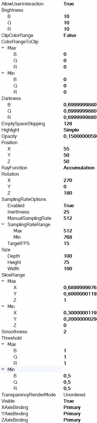
Properties tree of VolumeModel
Ray Function
RayFunction property allows choosing one of the three ways of voxel sampling and composition available in LightningChart Volume Rendering Engine:
- Accumulation collects and combines as much data as possible. The visualization which is produced by this technique looks like a semi-transparent gel. The figure below shows an example of Accumulation application visualizing a medical dataset.
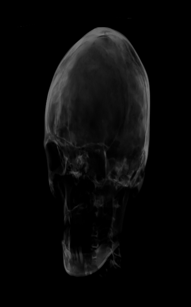
Example of a medical application for the RayFunction.Accumulation
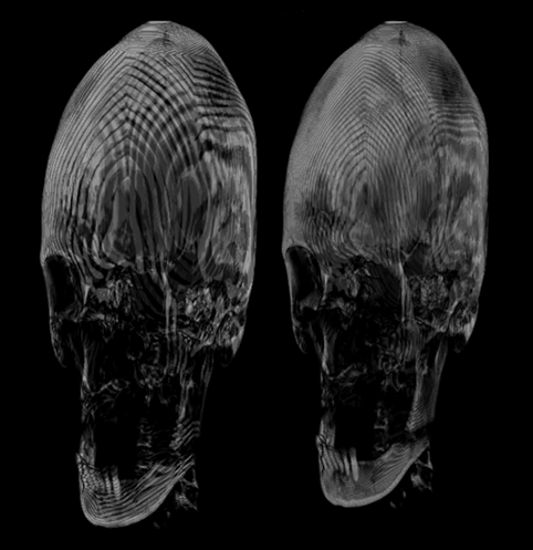
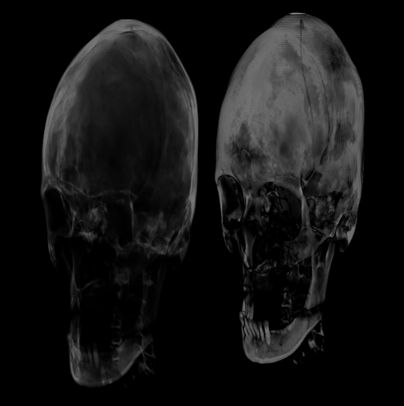
- MaximalIntensity takes into account only the brightest values sampled by the ray. Visually it provides a very similar result to X-ray images. It allows to get an additional information about the internal structure of the object. MaximalIntensity applications for skeleton visualization and ultrasound wave’s interference simulation are shown below.
Examples of a Maximum Intensity Ray Function application
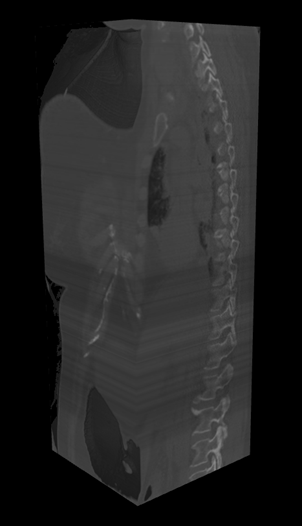
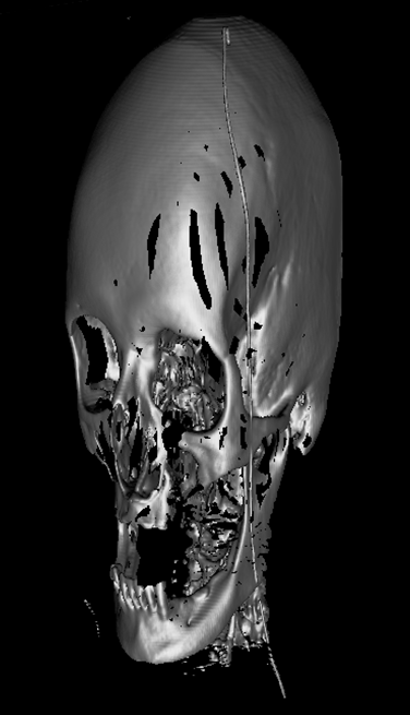
- Isosurface draws the model surface in a way that it looks like a polygonal model rendering. The result is very similar to those produced by Indirect Volume Rendering. Figures show examples of Isosurface applications for the visualization of human skull CT and simulation of water flow.

Examples of an Isosurface Ray Function application
Threshold
The Volume Rendering Engine can apply a threshold range (Threshold property) to the VolumeModel. Threshold removes colors outside the range. Every color channel (R, G or B) can have its own range, where values are between 0.0 and 1.0. The voxel is visualized only if the corresponding color values are lower than the high boundary, and higher than the low boundary at all the channels. This property is not taken into consideration by the mouse hit test.
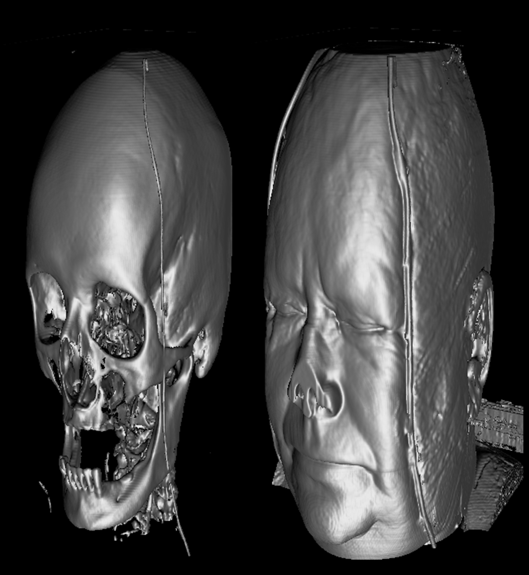
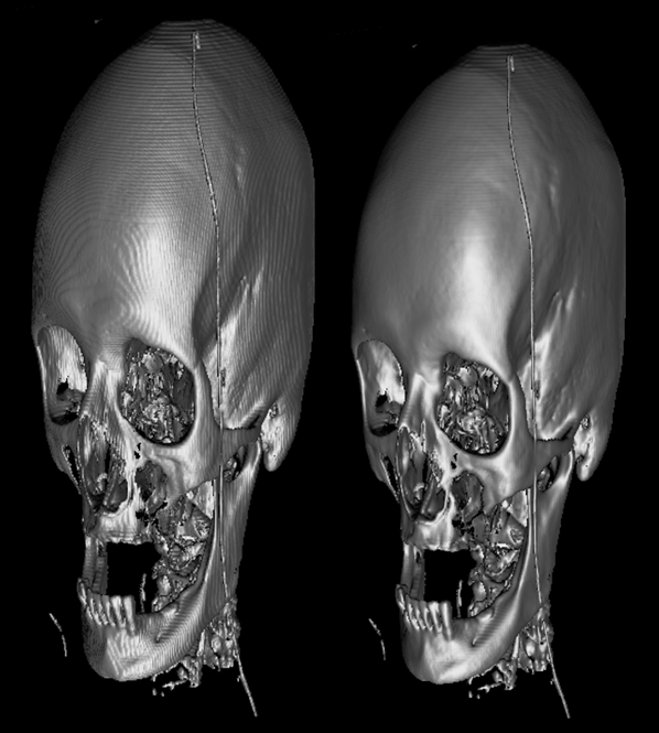
Example of two different threshold settings. Threshold.Max is same for both images, and equal 1.0. On the left, Threshold.Min = (0.5f, 0.5f, 0.5f), which cut away skin and soft tissues. On the right, Threshold.Min = (0.2f, 0.2f, 0.2f). RayFunction = Isosurface.
Color clipping
Volume models have ClipColorRange and ColorRangeToClip properties, which like Threshold, can be used to clip certain colors from the model. However, they work the opposite way. Color clipping doesn’t render colors within the defined color ranges, whereas Threshold removes colors outside the range.
ClipColorRange controls whether color clipping is enabled or not. ColorRangeToClip allows setting the actual color ranges that should be removed. Minimum and maximum clip values can be set via Min and Max properties for each color channel separately. Alternatively, all values can be modified simultaneously by assigning RangeRGB object to ColorRangeToClip. The clipped values should be between 0.0 and 1.0. After the ranges have been set, each color combination that is within the defined ranges will be clipped. Clipping takes all color channels into account simultaneously.
// Enabling color clipping.
_chart.View3D.VolumeModels[0].ClipColorRange = true;

// Modifying a single channel value.
_chart.View3D.VolumeModels[0].ColorRangeToClip.Min.R = 0.1;

// Assigning all clip ranges simultaneously.
_chart.View3D.VolumeModels[0].ColorRangeToClip =
    new RangeRGB(new PointRGB(0, 0, 0), new PointRGB(0.2, 0.2, 0.2));
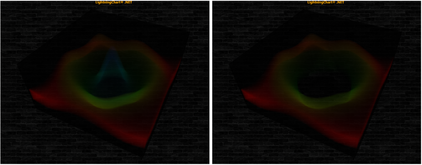
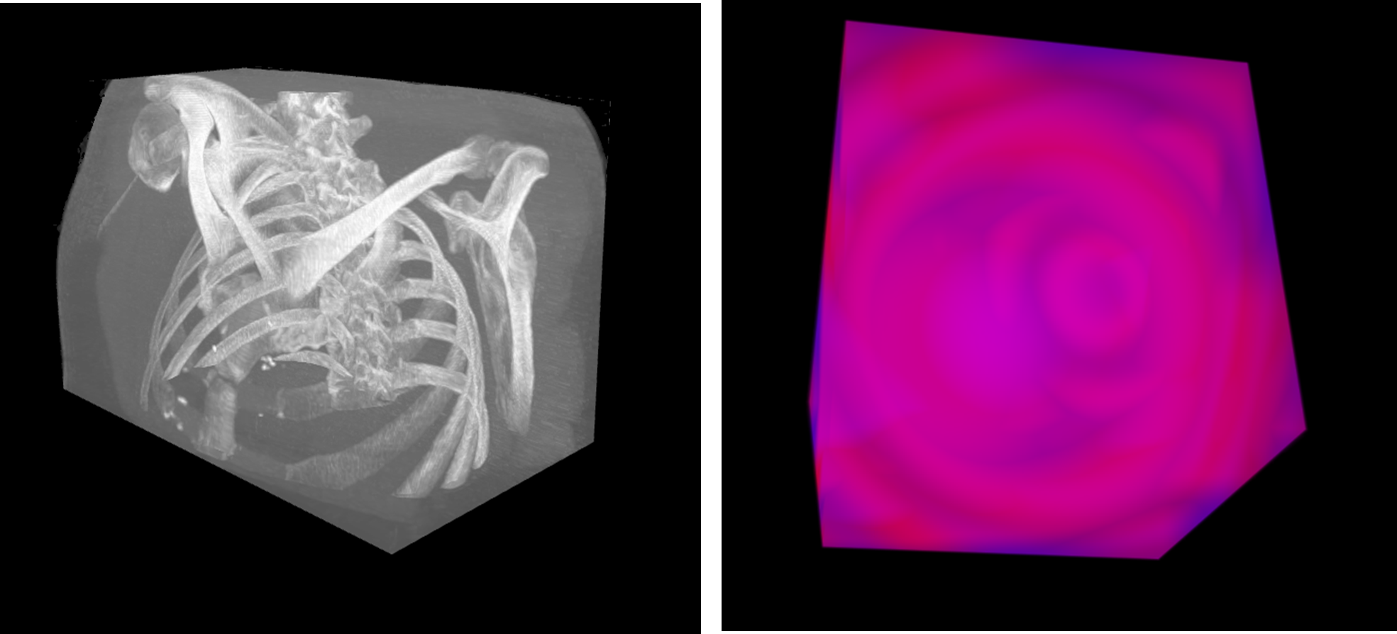
Original Volume Model on the left. On the right, color clipping is used to remove the blue channel.
Slice Range
SliceRange property allows cutting away a part of the VolumeModel along X-, Y- or Z-axis. It is a very useful tool for the exploration of the object’s internal structure. SliceRange contains two boundaries, Min and Max, both of which are represented by three pointing float values (values are between 0.0 and 1.0).
Example of Accumulation Ray Function and SliceRange modification
Sampling Rate Options
Sampling Rate is a very important property to the final image quality. It defines how often the volume dataset is sampled along the ray’s track. A higher Sampling Rate produces better quality but requires more powerful hardware. Sampling Rate influences RayFunction options, especially Accumulation. Artefacts produced by low sampling rate are less noticeable when using MaximalIntensity. Furthermore, Isosurface can be too sharp at a very high sampling rate. Usually, the sweet spot equals to the number of voxels on the side which is placed along the ray tracks.
SamplingRateOptions contains several options for Sampling Rate Manager. Sampling Rate Manager is needed to reach the optimal balance between quality and frame rate for a hardware. By default, Sampling Rate Manager is turned on by the property Enabled being set true. If set false, ManualSamplingRate value will be used. SamplingRateRange defines the boundaries for Sampling Rate Manager. Inertness specifies how rapid is the reaction of sampling rate in case of performance changes. TargetFPS is a target value, which sampling rate manager tries to achieve.
Example of low sampling rate: 32(left), 64(right)
Smoothness
Smoothness property prevents too high details of the surface. It smoothens the surface of the model and reduces some noise and other artifacts.
Example of too high sampling rate, fixed by smoothness property. RayFunction = Isosurface.
EmptySpaceSkipping
EmptySpaceSkipping property defines a resolution of empty space, skipping sampling. A low value (16-32) of EmptySpaceSkipping improves the performance but can cause artifacts in the model edges.
Example of too low EmptySpaceSkipping property value. RayFunction = Isosurface.
Opacity
Opacity specifies the behavior of Accumulation option of RayFunction. The lower the Opacity, the more transparent the object will be.
Example of Accumulation Ray Function Opacity modification: 15% (left), 45% (right).
Transfer function: Brightness and Darkness
One of the very basic method to customize the look of a volumetric rendering is to use a transfer function. Brightness and Darkness properties define the image’s transfer function. It is represented by the linear function:
output = Brightness * ( input - Darkness ),
where Darkness works as Subtrahend for original RGB colors, while Brightness works as Coefficient. If Brightness >1, corresponding RGB values in output will be brighter.
Examples
To see feature demonstration as example, check VolumeHead, VolumeFlow, VolumeGeo, VolumeSkeleton, VolumeWaveInterference, ColoringVolumeModel and TranslucentChart3D from our Demo.