Signal tools
LightningChart primarily is data visualization component. The SignalTools is small package for our users’ convenience, if they just need simple things in addition to charting. Signal Tools contains several components:
SignalReader - generates real-time data stream reading signal files in different formats: WAV (PCM), sid (biosignal file with marking), ssd (LightningChart's sampled signal data format). The playback can be automatically restarted with looping option;
AudioInput - Reads real-time sampled data stream from sound card line-in (using e.g. microphone) through DirectSound. The data can be forwarded to chart, AudioOutput or your own data target;
SignalGenerator - SignalGenerator is a multi-functional signal generator component. It allows combining different waveform types into single, real-time output signal. The waveform components can be set with a built-in user interface or by code;
SpectrumCalculator - Converts data between time domain and frequency domain using Fast Fourier transform (FFT) algorithm. Optimal for calculating FFT conversion and power spectrum of sampled signal data;
AudioOutput - Allows real-time data stream playback via sound card line-out (using e.g. speakers) through DirectSound. The data can be fetched from SignalGenerator, SignalReader, AudioInput or other data source.
Signal filters - SignalProcessing namespace has built-in digital signal filters (Finite Impulse Response (FIR) filters and Infinite Impulse Response (IIR) filters).
SignalGenerator component
SignalGenerator component can be used to generate real-time signal. The signal is produced as the sum of different waveforms. Several SignalGenerator components can be linked by master-slave relationship, to produce a synchronized, multi-channel output. SignalGenerator is very useful when developing signal monitoring or data acquisition software with LightningChart.
 Signal generator component with Sine page selected.
The waveforms are divided into following categories: Sine, Square, Triangle, Noise, Frequency sweep, and Amplitude sweep. Respective tab pages for them can be seen in the component. In Sine page, sine waveforms can be added. In Square and Triangle pages, square and triangle waveforms can be added respectively. In Noise page, random noise waveforms can be generated. In Frequency and Amplitude sweep pages, frequency and amplitude sweeps can be added. In All page, all the waveforms can be set in a stacked view.
To see EventMarkers used in example, check Oscilloscope, SignalGenerator to speakers, Intensity persistent layer, ExampleHiSpeedXY, ExampleAreaSeriesRealTimeXY, ExampleFFT, ExampleLissajousXY from our Demo.
Sampling frequency, Output interval and Factor
SamplingFrequency tells how many signal points are generated per second. Higher sampling frequency produces more accurate signal but comes with a cost of increased dataflow and overhead. With high sampling frequency, signals containing high frequencies can be presented. Sampling frequency must be more than twice the maximum signal frequency to fulfill Nyquist sampling theorem.
OutputInterval sets the preferred interval of calculated output samples, in milliseconds. For example, if OutputInterval is set 100, a bundle of samples is received 10 times per second, after every 100 ms period. Using lower values will give smoother real-time monitoring output. Note that OutputInterval is not accurate and may vary with computer load. The output data stream automatically generates more samples if the period has been longer than expected. The data stream will get in shape also with high data rates and under heavy computer overhead.
Factor multiplies the output samples by selected value. For example, to generate mV signal instead of V signal, set Factor to 1E-3.
Sine waveforms
Sine waveform is constructed with Amplitude, Offset, Frequency and DelayMs parameters. Amplitude is the maximum voltage difference from zero level. Note that the total range is bipolar. Peak-to-peak value will be 2 * Amplitude. Offset is DC level added to the signal. In other words, positive values shift the signal up and negative values shift it down in the value range. Frequency tells the signal cycle count in Hertz. One cycle per second is frequency of 1 Hertz. DelayMs delays in the signal in milliseconds.
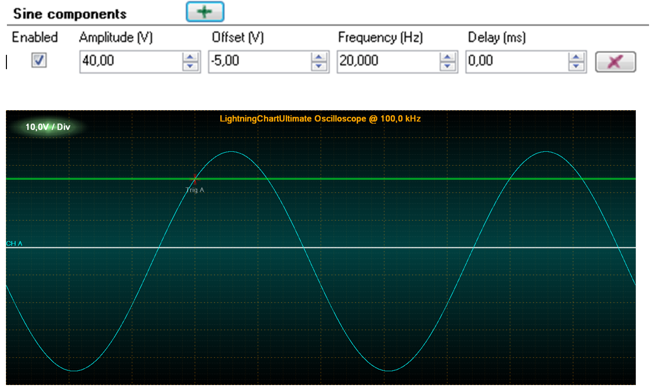 A simple sine waveform signal with settings above.
 The signal of two sine waveforms with their settings above.
Square waveforms
Square waveform has one more parameter compared to sine waveforms, Symmetry. The range for Symmetry is 0…1. Symmetry tells how long the signal stays in high state, related to cycle period. With a value of 0.5 the low and high states of the signal are of equal lengths.
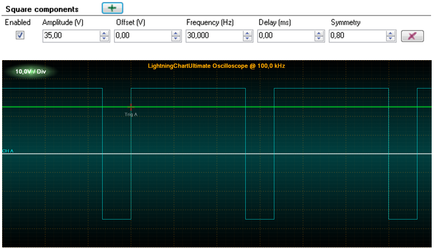 One square waveform signal, with symmetry of 0.8. Settings above.
Triangle waveforms
Triangle waveform also has Symmetry parameter. It controls the way the triangles lean. 0.5 is the value for symmetrical triangle. Values under 0.5 lean left and values over it lean right.
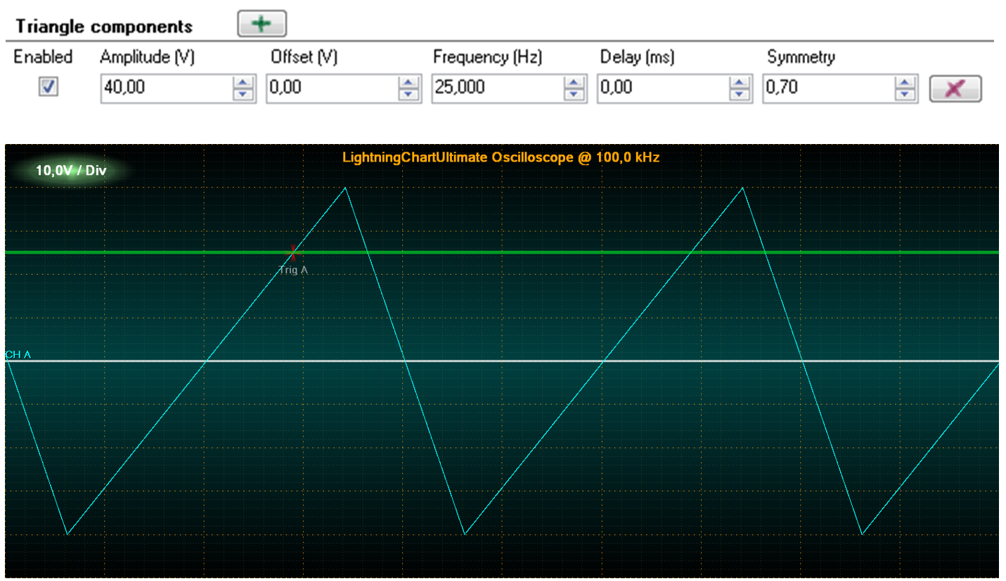 One triangle waveform signal, with symmetry of 0.7.
Noise waveforms
Noise waveform is a randomly generated signal. Points get randomized between -Amplitude and +Amplitude.
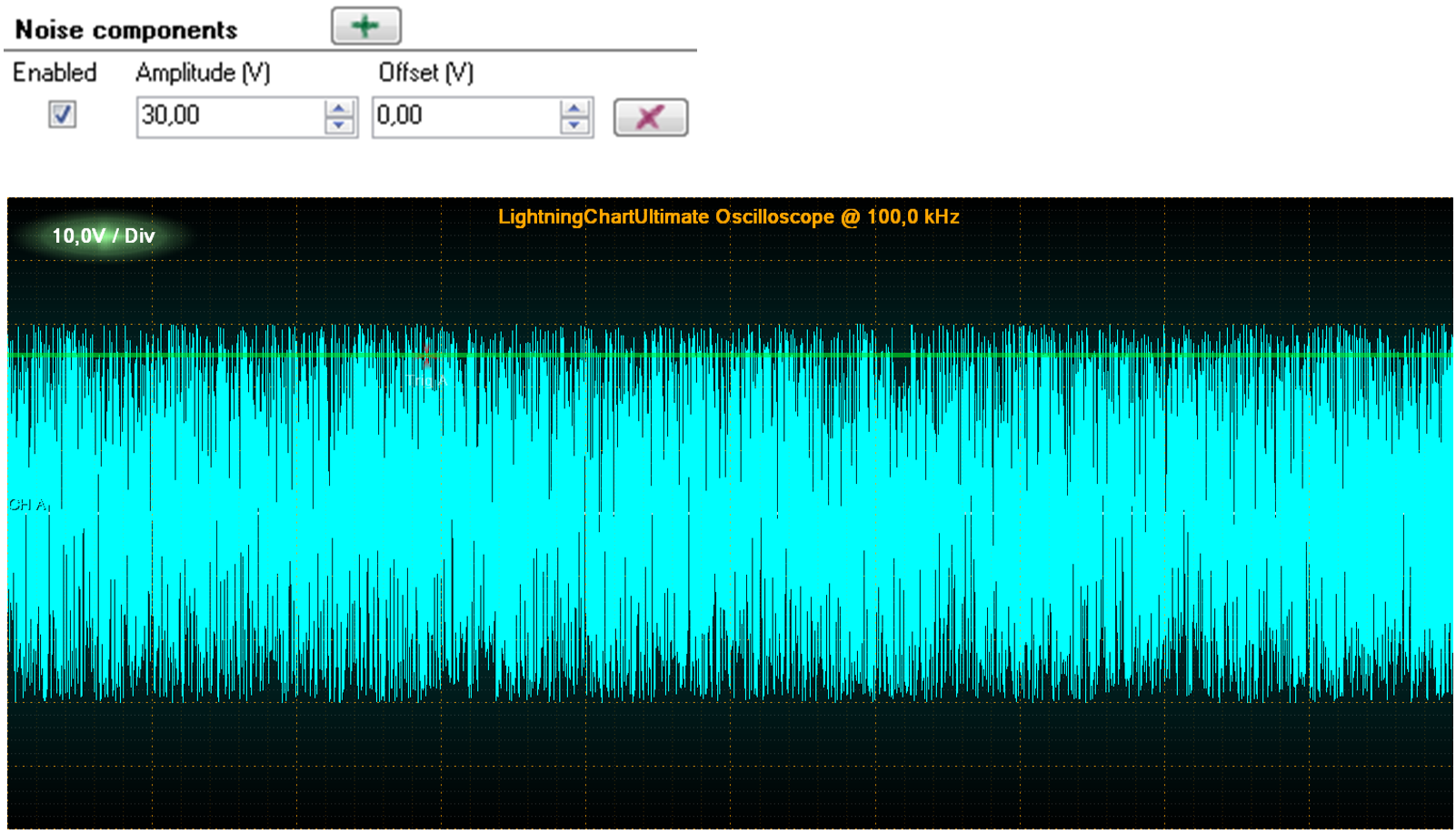 Noise waveform signal generating random data points between amplidutes -30 and +30.
Frequency sweeps
Frequency sine sweep runs from frequency 1 to frequency 2 in given time period, with constant amplitude. Use FrequencyFrom to set the start frequency, FrequencyTo to set the end frequency, Amplitude to set the constant amplitude, and DurationMs to set the duration in milliseconds.
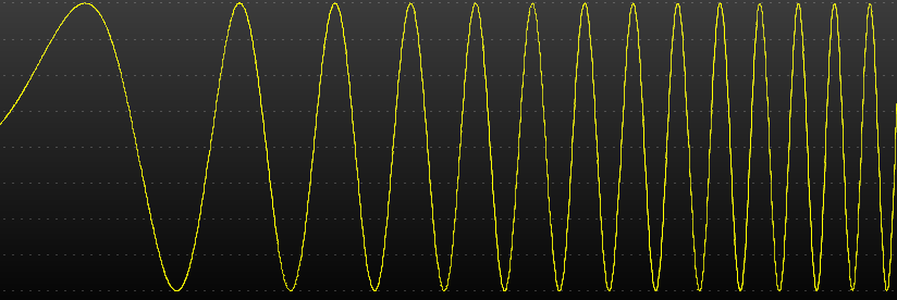 Frequency sweep
Amplitude sweeps
Amplitude sine sweep runs from amplitude 1 to amplitude 2 in given time period, with constant frequency. Use AmplitudeFrom to set the start amplitude, AmplitudeTo to set the end amplitude, Frequency to set the constant frequency, and DurationMs to set the duration in milliseconds.
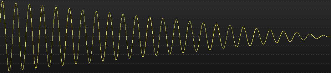 Amplitude sweep
Starting and stopping
Start the generator by pressing Start button or calling Start method. Stop the generator by pressing Stop button or calling StopRequest method. Stopped event will fire when stopping is complete.
Multi-channel generator with master-slave configuration
Several SignalGenerator components can be connected to produce a synchronized, multi-channel output.
MasterGenerator controls the sampling frequency, start, stop and output of all generators. It produces the first channel in the output data stream.
Slave generators are connected to master generator by assigning their MasterGenerator property. Define the signal waveforms freely. Slave generators are started and stopped by the master generator. They get the output data stream channel index in the connection order. Slave generators must be connected before starting the master generator.
Output data stream
The output data stream consists of two-dimensional arrays, obtained via DataGenerated event handler. Generally, the event is raised after every OutputInterval.
The event handler obtains a reference to a samples array, and a time stamp for the first samples bundle received during this interval. The first dimension of samples array represents channels and the second the samples for each channel. All channels have equal sample count.
Raising DataGenerated event:
m_signalGenerator.DataGenerated += m_signalGenerator_DataGenerated;

private void m_signalGenerator_DataGenerated(DataGeneratedEventArgs args)
{
	// Event code
{
To investigate the channel count of the data stream, get the length of first dimension:
channelCount = args.Samples.Length;
To get the sample count of a channel:
sampleBundleCount = args.Samples[0].Length;
The following code will demonstrate how to forward the output data directly to SampleDataSeries list of LightningChart while updating real-time monitoring scroll position.
private void m_signalGenerator_DataGenerated(DataGeneratedEventArgs args)
{
	chart.BeginUpdate();
	int channelIndex = 0;
	int sampleBundleCount = args.Samples[0].Length;
	foreach (SampleDataSeries series in chart.ViewXY.SampleDataSeries)
	{
            series.AddSamples(args.Samples[channelIndex++], false);
	}

	//Set latest scroll position x
    newestX = args.FirstSampleTimeStamp + (double)(sampleBundleCount - 1) / generatorSamplingFrequency;
	chart.ViewXY.XAxes[0].ScrollPosition = newestX;
	chart.EndUpdate();
}
Note that with args.Samples[0] you can access the master generator’s data. args.Samples[1] gives access to first slave generator data, args.Samples[2] to second slave etc.
SignalReader component
SignalReader component allows reading data from a signal source file and playing it back with selected rate. SignalReader output data stream format is similar to SignalGenerator. SignalReader component currently supports wav, ssd and sid formats. From version 12.5 SignalReader can read not only 16-bit WAV audio files, but also 24-bit and 32-bit (integer) WAV files.
Key properties
FileName defines the file to be opened, for example “c:\wavedata\audioclip1.wav”
Factor sets the output factor. Raw signal samples are multiplied by this value.
OutputInterval is similar to SignalGenerator’s property.
IsLooping allows file read to jump to the beginning of the file, when the end of file has been reached.
After the file has been opened, the following properties can be used to get information about the file:
ChannelCount: the channel count of the file.
SamplingFrequency: sampling frequency in Hz.
FileSize: File size in bytes.
Length: Sample count for each channel. It may not be exact for all signal file formats.
IsReaderEnabled: Status telling is the component started and reading data. If Looping is set to false and end of file is reached, IsReaderEnabled will change to false.
Opening file quickly for playback
Call OpenFile(…) method supplied with a file name. The file name must have an extension of supported formats. Then, call Start() method.
signalReader.OpenFile(“c:\\wavedata\\audioclip1.wav”);
signalReader.Start();
A playback of a PCM-formatted WAV file is then started.
The playback can be stopped by calling StopRequest() method.
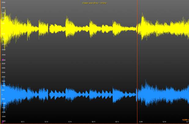 SignalReader reads a wav file and LightningChart SampleDataSeries draw the signal. A cursor line is used to mark the current reading position and the X-axis scroll position.
To see EventMarkers used in example, check ExampleSignalReader, ExampleWaveFFT, ExampleAudioSpectrogram3D, ExamplePersistentFFT from our Demo.
AudioInput component
AudioInput component allows user to capture signal from Windows’ recording device to System.Double values. These values can then be rendered on LightningChart, sent to an AudioOutput component, saved to a file etc.
Properties
BitsPerSample – Gets or sets how many bits are allocated per sample. Supported values are 8 and 16. If other values are used, 16 is used instead. It can be set when IsInputEnabled is false.
IsInputEnabled – Gets or sets the state of this instance (i.e. starts or stops it). Setting this property true is the same as calling Start method where false is the same as calling Stop method.
IsStereo – Gets or sets whether to use two channels (stereo) or just one (mono). Can be set when IsInputEnabled is false.
RecordingDevice – Gets or sets the current recording device. Can be set when IsInputEnabled is false. By setting this property to null, Windows' default recording device is used.
SamplesPerSecond – Gets or sets the sampling frequency. Can be set when IsInputEnabled is false.
ThreadInvoking – Gets or sets whether this instance automatically synchronizes its events to the main UI thread, hence eliminating the need to call Control.Invoke method on caller's side.
Volume – Gets or sets the volume, ranging from 0 to 100. Can be set when IsInputEnabled is false.
Methods
GetRecordingDevices – Use this static method to get a list of available Windows recording devices.
RequestStop – Signals this AudioInput instance to stop. Stop does not occur immediately after exiting this method. By subscribing to Stopped event, caller is notified when everything has stopped.
Start – Starts reading audio from selected recording device. Started event is triggered when internal thread is about to start.
Events
DataGenerated – Occurs when a new set of audio data has been generated. Data and its first sample’s time stamp can be read from a DataGeneratedEventArgs object that is provided as a parameter.
Started – Occurs when an audio input has been started. StartedEventArgs object that is provided as a parameter, contains three public fields: BitsPerSample, ChannelCount and SamplesPerSecond.
Stopped – Occurs when the audio input has been stopped.
Usage (WinForms)
Creation
Create a new AudioInput instance either manually in the source code or by dragging and dropping it from Visual Studio’s toolbox on to the form, user control etc.
If there is no need to show the GUI (i.e. if using an own GUI or controlling AudioInput object from the source code) then set Visible property false. Parent property is always recommended to be set so that when the parent control is disposed, AudioInput instance gets disposed automatically. If there is no parent, then Dispose method should be called when AudioInput instance is no longer needed. If a new AudioInput instance is created via Visual Studio’s toolbox, Parent property is automatically set.
Event handling
To get new samples from AudioInput instance, the user needs to subscribe at least to DataGenerated event. When DataGenerated event is triggered, new samples and the first sample time stamp from a DataGeneratedEventArgs object are provided as a parameter.
Subscribe to Started event to know when AudioInput instance has started its audio sampling task. A StartedEventArgs object provides information about AudioInput as a parameter, for example the number of bits per sample, is the stream audio mono or stereo, and how many samples per second are generated.
Subscribe to Stopped event to know when AudioInput instance has stopped. The event has no parameters, and its sole purpose is to tell user when everything has been stopped.
Configuring
Set ThreadInvoking = true to allow an AudioInput instance to synchronize its events to the main UI thread automatically but make sure that the AudioInput instance has a valid parent control. ThreadInvoking is set to false by default so do not forget to call Control.Invoke method if updating GUI in DataGenerated event handler.
Setting RecordingDevice property allows using other Windows’ recording devices than the default one. Get all available recording devices by using AudioInput’s static method GetRecordingDevices.
Volume can be controlled via Volume property. Valid values are from 0 to 100 where 0 means mute and 100 maximum volume. The volume can also be set when AudioInput instance is enabled (i.e. generating samples).
Set SamplesPerSecond property to use difference sampling rate than the default (44100 Hz). Setting this property while AudioInput instance is enabled has no effect.
To use mono audio instead of stereo (default), set IsStereo to false. Setting this property while AudioInput instance is enabled has no effect.
If 8 bits per sample is preferred rather than 16 (default), set BitsPerSample property to 8. Valid values are 8 and 16 (default). This limitation comes from PCM wave format. Setting this property while AudioInput instance is enabled has no effect.
Starting
To start AudioInput instance, either set IsInputEnabled property true, or call Start method. DataGenerated event then provides a new set of audio samples which can e.g. be rendered using LightningChart instance.
Stopping
To stop AudioInput instance, set IsInputEnabled to false, or call RequestStop method. RequestStop method does not stop instantly. Instead, it signals AudioInput instance to stop as soon as it is possible. Subscribe to Stopped event to know when AudioInput instance has stopped.
Usage (WPF)
This chapter describes the usage of WPF version of AudioInput class. WPF version of AudioInput works mostly the same way as WinForms version. However, there are a couple of things that a WPF user should be aware of.
Creation
Create a new AudioInput instance either manually in code-behind or by dragging and dropping it from Visual Studio’s toolbox on to a window, user control etc.
If there is no need to show GUI (i.e. if using an own GUI or AudioInput object is controlled from the source code) then use AudioInput from LightningChartLib.WPF.SignalProcessing namespace. This particular class is derived from FrameworkElement and all its properties are bindable. For convenience, after having installed LightningChart® .NET SDK, LightningChartLib.WPF.SignalProcessing.AudioInput can also be found from Visual Studio’s toolbox so it can be dropped to a window, user control etc. and then moved in the XAML code to wherever it is needed. Necessary XML namespace will be added automatically this way.
There is also a ready-made GUI for AudioInput. It can be found in LightningChartLib.WPF.SignalProcessing.Gui namespace. Visual Studio’s toolbox also has it after LightningChart® .NET SDK has been installed. Note that this is just a GUI for AudioInput class, but it contains an instance of AudioInput class which can be accessed. In other words, there is no need to create a new separate AudioInput instance.
To see EventMarkers used in example, check ExampleAudioInput, ExampleAudioInputSpectrogram from our Demo.
AudioOutput component
AudioOutput component allows user to convert System.Double signal data into an audio stream which is then played back through speakers or sent to Line-out connector of sound device.
Properties
Balance – Gets or sets audio playback balance. Valid values are between -100 to 100. -100 means that audio is played only through the left speaker. 0 means that both speakers output audio. 100 means that audio is played only through the right speaker.
BitsPerSample – Gets or sets how many bits are allocated per sample. Supported values are 8 and 16. If any other value is used, 16 is used instead. It can be set when IsOutputEnabled is false.
IsOutputEnabled – Gets or sets the state of this instance (i.e. starts or stops it). Setting this property true is the same as calling Start method where false is the same as calling Stop method.
IsStereo – Gets or sets whether to use two channels (stereo) or just one (mono). It can be set when IsOutputEnabled is false.
PlaybackDevice – Gets or sets the current playback device. Can be set when IsOutputEnabled is false. By setting this property null, Windows' default playback device is used.
SamplesPerSecond – Gets or sets sampling frequency. Can be set when IsOutputEnabled is false.
Volume – Gets or sets volume (0-100). Can be set when IsOutputEnabled is false.
To see EventMarkers used in example, check ExampleAudioOutputSignalReader, ExampleAudioOutputSignalGenerator from our Demo.
SpectrumCalculator component
SpectrumCalculator component allows conversion between time domain and frequency domain.
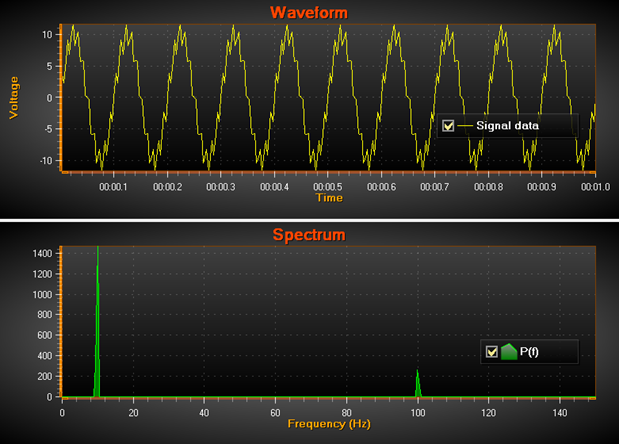 Example of source signal data (top) converted to frequency domain (bottom). Signal sampling frequency = 300 Hz, thus frequency scale is 300/2 = 150 Hz. The strong sine base line is 10 Hz (10 cycles / sec). Smaller signal of 100 Hz is added as noise. Both spikes are found in the power spectrum.
The following public methods are available:
- CalculateForward(double[] samples, out double[] fftData) - Converts time domain signal data to frequency domain by using FFT. Output fftData contains also negative values. Input and output data arrays must be of equal length. The length is the resolution of the data, spreading from 0 Hz to sampling frequency / 2 with equal frequency interval between output values.
- CalculateForward(float[] samples, out float[] fftData) – Similar to the previous method, but for single accuracy floating point values. CalculateBackward(double[] fftData, out double[] samples) - Converts frequency domain data to time domain. Makes signal samples from FFT data. Sample count equals input fftData length.
- CalculateBackward(float[] fftData, out float[] samples) – Similar to the previous method, but for single accuracy floating point values.
- PowerSpectrum(double[] samples, out double[] fftData) - Calculates power spectrum of signal data. Is the same as CalculateForward, but with absolute output values.
- PowerSpectrum(float[] samples, out float[] fftData) – Similar to the previous method, but for single accuracy floating point values.
- PowerSpectrumOverlapped(double[] samples, int fftWindowLength, double overlapPercent, out double[] fftData, out int processedSampleCount) - Calculates the power spectrum by shifting the calculation windows inside source signal samples data, by overlap percent. Signal data must be longer than given FFT window length. The output FFT data is the length of fftWindowLength which is not necessarily the same as the length of the source data. The output data has absolute values.
To see EventMarkers used in example, check ExampleFFT from our Demo.
Signal filters
SignalProcessing namespace has built-in digital signal filters. They are designed to filter out unwanted frequencies from the acquired signal data. There are two types of filters. Finite Impulse Response (FIR) filters are amplitude stable, constant phase shift filters, which cause a constant lag in the data. The higher the factor count (taps), the longer the delay. Infinite Impulse Response (IIR) filters are minimal-lag filters, but introduce phase shift depending on the input frequency, and are unstable if designed poorly.
SignalProcessing namespace must be used in order to utilize signal filters. This allows creating FIRFilter and IIRFilter objects. To filter the data, call FilterData(rawData, out filteredData) method of either of the objects to use the respective filter.
using LightningChartLib.Wpf.SignalProcessing;

// Creating a FIR filter and filtersamples with it.
FIRFilter _firFilter = new FIRFilter();
double[] filteredSamples;
_firFilter.FilterData(rawData, out filteredSamples);
The filter classes have several methods regarding their behavior. SetFactor() for both filters and SetABFactors() for IIR filters can be used to modify the factors controlling for instance the data lag and unstable output limits. GetDelay() gets the current data lag while Reset() resets the internal delay and filtering buffers.
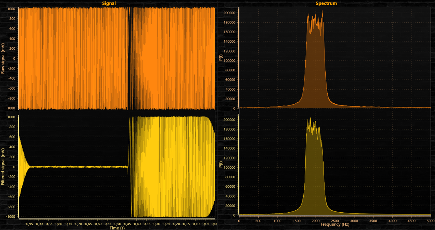 Raw, unfiltered signal on the top, filtered signal on the bottom.
To see EventMarkers used in example, check ExampleSignalFilters from our Demo.